Overview
Strong demand for contract manufacturing coupled with a shortage of skilled labor places new stress on companies trying to maintain product quality and grow their businesses. Training unskilled workers for specific assembly and test jobs takes time, and may prove unsatisfactory if quality cannot be maintained. Further, with the added requirements of ISO 9000 certification, faults in procedure or documentation could create problems for the company's customers and reputation. PC-based test automation addresses many of these problems, particularly for contract cable assembly shops. This article discusses the approach one cable tester manufacturer has taken to automate test, fault isolation, labeling, and documentation to ensure test consistency and reduce susceptibility to human error.
Cable Tester Automation
Strong demand for contract manufacturing coupled with a shortage of skilled labor places new stress on companies trying to maintain product quality and grow their businesses. Training unskilled workers for specific assembly and test jobs takes time, and may prove unsatisfactory if quality cannot be maintained. Further, with the added requirements of ISO 9000 certification, faults in procedure or documentation could create problems for the company's customers and its reputation. PC-based test automation addresses many of these problems, particularly for contract cable assembly shops and OEMs. We review the approach CAMI Research Inc. has taken with the CableEye® tester to automate test, fault isolation, labeling, and documentation to ensure test consistency and reduce susceptibility to human error
Manufacturing errors are inevitable. Through quality control, we seek to keep those errors to an absolute minimum. Achieving this depends largely on reducing human error in assembly and test. Our PC-based approach to cable testing advances the technology by:
1 - maintaining a secure, accurate cable database,2 - displaying cable wiring and errors graphically,
3 - automating control of the test process, and
4 - providing high-quality documentation.
The balance of this article shows exactly how these capabilities help the operator avoid errors and improve throughput. It is important to note that the attributes of our tester result from the PC's high-resolution color graphic display, hard disk mass storage, programmability, and graphics printer drivers. Lacking a PC, these attributes would not be possible.
Benefits of a Computerized Database
Reliable testing depends absolutely on accurate comparison data ("golden" cable data). Given accurate data, we must also ensure that the operator loads this data into the tester flawlessly. Uncertainty on either of these requirements can only reduce our confidence in the test results. A computerized database offers many advantages in these regards:
1 - The cable data you store will never change and can be managed by one responsible quality control engineer. You may then distribute it by the company's network to remote PC-based test stations.
2 - Data backup, a critical element of any system wide quality program, is easy and fast, and can even be made automatic.
3 - You may easily exchange cable data with your customers, or with an overseas factory, using modems or e-mail. By entering cable specifications in computer-readable form at the beginning, you are simultaneously creating model data for the tester, and eliminating any chance for keystroke or transcription errors. This same data may then be used to generate schematics and documentation automatically, eliminating another potential source of error.
4 - You may save cables under their true part number. You no longer need a "signature" or other arcane numbering scheme with which to code cables. Using a cable's part number to identify it in the database is more meaningful, and reduces the chance of operator error in loading data, recording results, or making labels.
5 - The database holds much more information than just cable wiring. With each record, our CableEye system stores the wire list and schematic, connector types, label text, and descriptive notes. The text you enter may be of arbitrary length and include vendor information, customer data, assembly or setup instructions, cost, related part numbers, color codes, and operator name.
Displaying Information Graphically
People more readily understand images than numbers. We take advantage of that fact by showing cable wiring graphically, and depicting cable faults with pictorial images rather than just as numbers alone. Figure 1 shows the wiring of a typical cable containing jumpers and crossovers.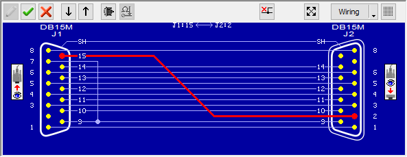
Software automatically computes the wiring schematic after a cable is measured. In this actual screen shot, the operator has highlighted one connection (in red) for review. In Figure 2, you see the graphic display that results from a single missing connection (the shield).
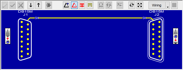
A numeric wire list appears on all printed documentation in addition to the graphic display, and can be shown on the screen with a single keystroke. The small icon near each connector shows the direction of view into the connector. Change the direction of view into either connector with a single keystroke for the most informative orientation. The operator may choose to display the wiring if a fault is detected, or rely only on LED lamps to reveal a PASS/FAIL condition.
Automating the Test Process
Test consistency plays a large role in determining reliability. By completely automating the test process after the operator attaches a cable, we eliminate any chance that testing or documentation will differ from one cable to the next. We accomplish this with "Macros," which are small programs assembled by the test engineer using English-language instructions. A Macro can be as short as three instructions, although we show a more typical one in Figure 3. Macros pause when they reach the instruction WAIT FOR PB to let the operator mount the next cable to be tested. When ready, a pushbutton on the tester, or a footswitch, is pressed to continue.
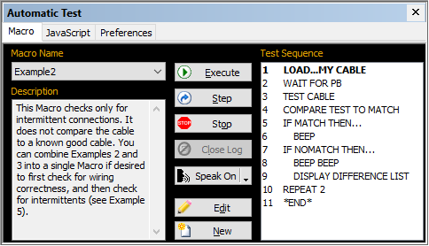
Figure 4 shows a Macro that prints labels for correct cable assemblies, logs test results to disk, and prints an error report (the "difference list") should any problems be found.
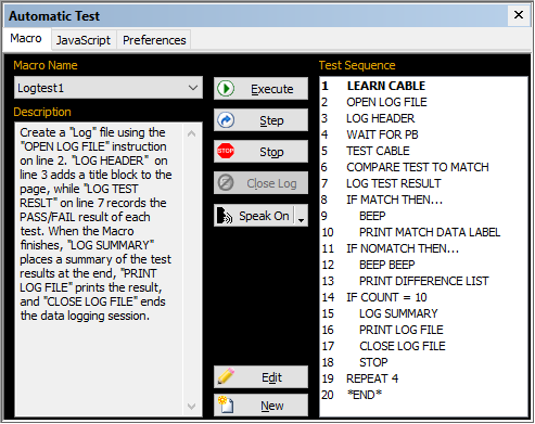
If errors are found, it prints an error report.
The first line of this Macro brings up an entry screen that allows the operator to enter the name of the assembly to be tested. Alternatively, you may use a bar code reader in place of the computer's keyboard to enter this information. If desired, you may embed the count value produced by the Macro within notes or label text to create serialized labels and documentation.
Reports and Labels
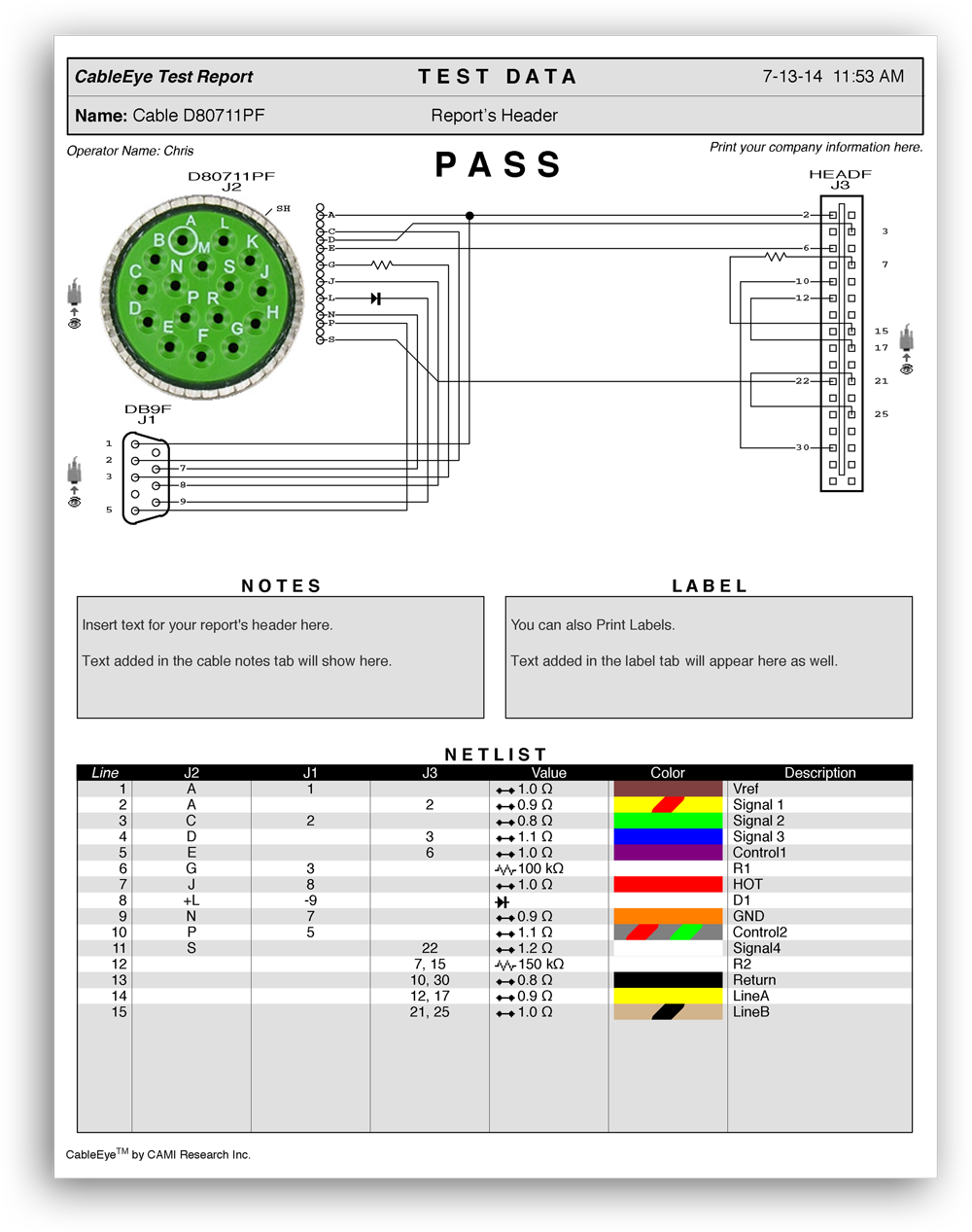
Documentation generated at test time certifies that an assembly has been tested and describes the result. You may produce a test sheet for each assembly, or a single report at the end of a batch summarizing the result. Figure 5 shows the item report, while Figure 6 gives the batch report. Your company's name may optionally be printed under the title block for reference by your customers.
Technician training
Our experience shows that test technicians who have not previously worked with PCs, experience a fairly short learning curve in adapting to this equipment. We rely on predictable, stable, menu-driven software with easy-to-understand messages, and an on-screen help system with page references to the User's Guide. Within a week, most technicians are comfortable with CableEye, productive, and have no wish to look back at their old benchtop testers.
Cost
PC-based test equipment relies on mass-produced, interchangeable, inexpensive computer hardware for all but the data acquisition task. CableEye systems require no more than a low-end PC (with USB interface) and a low-end printer both of which you may well have surplus in storage and, if not, can be purchased for less than $1000 total. As a result, your cost to set up a PC-based test station is extremely attractive. Pricing for a 128-point CableEye tester with software and CB15 CB board set is $1295, and the complete station cost remains under $2500 even if a new pc and printer is purchased. Expand the system to over 2560 test points at $495 per 128-point module. When weighed against the saved technician time resulting from graphic wiring display during rework, and the added benefits of a secure cable database, test consistency, and full-schematic documentation, payback will be on the order of months for a busy cable shop.After only a few hours of use we have reduced production time by DAYS.
Richard Eich, Electronics Design Engineer
Handi Quilter Inc.
Hear more from our customers ...
Smart Assembly & Test | Article
CableEye test systeems provide numerous automation options, including automated relay operation for controlling lock & release latches, diverter gates, and molding equipment. Learn more about our smart options ...
Cable and Harness Manufacturing: Smart Assembly & Test
Create smart cable & harness assembly and test lines,
and handle mixed-model value streams. Read now!
Test Automation Capabilities | Video
Easily control the workflow of your test with Macros, and use the options to control tower lights, LEDs, audible tones, labels, latches and more. Scan barcodes to initiate tests and input data. See an automated test in action ...
Video Duration: 2:13 min
CableEye® Automation-Ready Cable and Wire Harness Test Systems
CableEye is a highly versatile, expandable and upgradable diagnostic and Pass/Fail check Cable and Harness Test System that’s PC-based. It’s used for assembly, prototyping, production, and QC of standard or custom wire cables and harnesses The entire suite of products is powered by the same easy-to-use operating software and, with the help of its signature easy-to-interpret color-coded graphics, instantly identifies not only when there is a fault, but what type of fault and where.
Low Voltage M2 Series
For diagnostic and Pass/Fail Testing - Find, display, log, & document continuity (opens, shorts, miswires, intermittent connections).
Low Voltage M3 Series
For all of the above plus resistance (contact, isolation, embedded), and diodes (orientation, forward voltage, reverse breakdown).
Low Voltage M4 Series
For all of the above plus precision resistance (4-wire), and capacitance (twist wire relationship, length of cable, length to break, capacitors).
Low Voltage and High Voltage HVX Series
For all as described for M3Z plus HiPot (dielectric withstand voltage and insulation resistance). 4-Wire Kelvin Measurement and Advanced Measurement Options (capacitance, twist wire relationship, length of cable, length to break, capacitors) are available.
Free 2-Week Trial
Experience a CableEye tester first-hand. See how your own cables and connectors can be auto-detected and accurately represented on our graphic-rich, touch screen compliant GUI. Find cable problems fast, and understand why customers tell us "... we can not live without CableEye" (Kabelservice), declaring it the "... best, easiest to use, system" (Digital Video Products).
No Credit Card. No Commitment to Purchase.
Limited availability. Schedule your Free Trial now!